|
|
|
|
Building a Ship Wheel
By Jeff Streba
|
|
|
Click on any picture to see a larger version.
Last summer my 17 year old boy answered an ad to help build a sail boat in order to sail around
the world doing research and humanitarian work. The boat was located in Mesa, Arizona, nowhere
near water. They call it the Argo and it is a 48 foot Ketch. The owner, Douglas, has plenty of
experience building boats. As a young man he built sailing vessels that raced around the world.
Last Thanksgiving we traveled to Mesa to meet Douglas, the crew, and work on the Argo. At that
time, the boat was nothing but an empty fiberglass hull. One evening, while sitting around
talking about the sailing adventure, Douglas brought out the pedestal for Argo. A pedestal is the
part of the ship that the wheel is attached to. I was moved by Douglas' vision; on one hand, he
has a 48 foot empty fiberglass hull in the middle of the desert, on the other hand, one of the
final pieces of the puzzle, the pedestal. The woodworker in me yearned to make the wheel for
Argo.
I have never made a ship wheel, I usually make furniture. However, I very much enjoy making
things I've never made before. For this project, Douglas outlined a few limiting factors: 1. The
wheel should be 36 inches in diameter. 2. It should not have exposed handles. Although it looks
cool on a pirate ship, on a small boat they get in the way. The handles need a ring. 3. The
wheel needs to slide onto a 1" straight shaft with a 1/4 key. Beyond that I could design it as I
pleased.
The first thing I did was look at images of old wheels on the internet. I was trying to get an
idea of how they were designed to hold together under all the rotational forces. A ship wheel is
a simple machine that is used to apply mechanical advantage to an axle to swivel the ships
rudder. The larger the diameter of the wheel, the more force will be transmitted to the rudder.
The Argo will have a rudder approximately 6 feet long and 2-1/2 feet wide. The wheel needs to be
designed strong enough to manage the forces of a rudder that size.
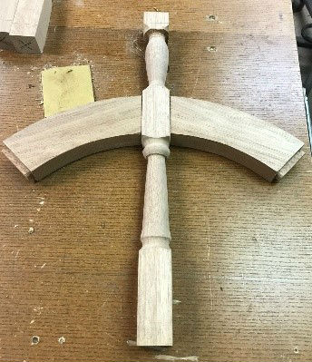
After having done my research, I deduced that the wheel will be made of 6 parts. I am not a
sailor so I do not know if there are formal names for each part so what follows is the names I
gave them.
Hub – the hub will be made of brass and is the part that slides onto the shaft of the pedestal.
Plates – the plates are also made of brass and bind the hub to the wood spokes.
Spokes – wood parts that radiate from the hub.
Spacers – wood pieces that are in between the spokes.
Supports – wood pieces that tie together the spokes and the spacers.
Ring – bent wood piece that forms the outside diameter of the ship wheel.
Once I figured out how ship wheels were built I made a formal drawing. I started the woodworking by first making the spacers. From the drawing, I knew the inside and
outside diameters. I made a master pattern then used it to trace the shape on each of the 8
spacers. The bandsaw was used to cut close to the line. To get a perfect radius I made a jig that
indexed and clamped the spacer so it could be flush trimmed on the router table. The problem
with this idea was that as the router bit hit the second half of the radius it would be cutting
against the grain as opposed to with it and chip out the wood. To solve this problem, I was able
to use the shaper, flip a straight cutter over, and run the machine counterclockwise. Half the
radius was cut on the router and the second half on the shaper. I cut 8 perfect parts.

|
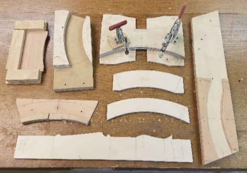
A variety of jigs and templates were used
in the build
|
|
|
Tenon and mortise joints on the spoke and spacers
|
The spacers attach to the spokes using Mortise and Tenon joints. I designed an 8 spoke wheel
and made a pattern of what I wanted it to look like. I then sized the wood and cut the mortises
using a router. To cut the tenons on the spacers I used a commercial tenon jig and the table
saw. The joints fit great.
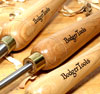
The next hurdle was to figure out how to use a lathe and turn the spokes. I have owned a lathe
for years but never bothered to learn how to use it; feeling that it was a completely different
direction of woodworking then I wanted to pursue. Using the pattern, I practiced techniques
that would allow me to make consistent parts. They turned out pretty good, no pun intended.
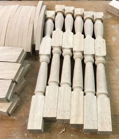
|
|
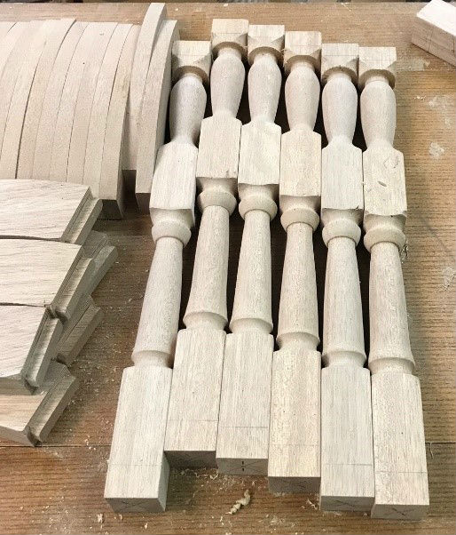
Some of the turned spokes, spacers and supports
|
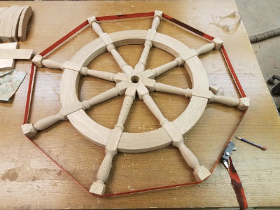
With the joints cut and the spokes turned, the last thing I needed to do before fitting everything
into a circle was trim the hub section of the spokes. The dry fit of the parts showed there was
no need for any modification. To this point, my design and build has proven to be good. I glued
the wheel together.
|
|
Glued and clamped up spokes and spacers
|

|
|
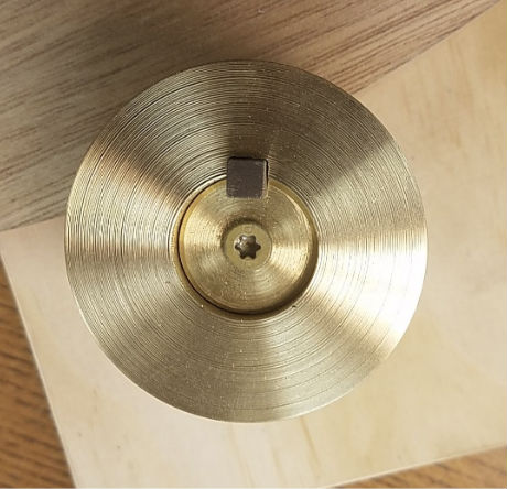
2-1/2" brass hub with key
|
The center of the wheel has a brass hub that will slide over the shaft on the pedestal. The hub
has a 1/4" key so when the hub turns so does the shaft. A friend that has a metal lathe helped me
make the hub. The hub slides into a hole at the base of the spokes.
The hole needed to be perpendicular to the plane of the wheel. My drill press will not reach to
the center of the wheel so I needed to find a different way. Drilling freehand was out of the
question. Routing with a template was feasible but not desirable. Some months earlier I bought
a tool from a yard sale that looked to be 30 years old and never used, it was still in the original
box. I had no idea what I would use it for but I thought for $5 it could sit in my shop for the next
30 years. This tool is called a multi-angle drill guide and it is a jig that attaches to an electric
hand drill that drills holes perpendicular to a plane or at an angle. I got my $5 out of it that day.
The hub slid in perfectly. I should also say that this a good argument for buying tools we don't
need.
As I was researching how wheels were put together I had to figure out how the shaft on the
pedestal was going to turn when the wheel was turned. The hub has a key so there is a positive
connection between the hub and the shaft. To make a positive connection between the rest of
the wheel and the hub I used two brass plates, one on each side of the wheel. The plates are
bolted to the hub and in turn the plates are also thru bolted to each spoke. When the wheel
turns so does the hub and shaft and the ship rudder.
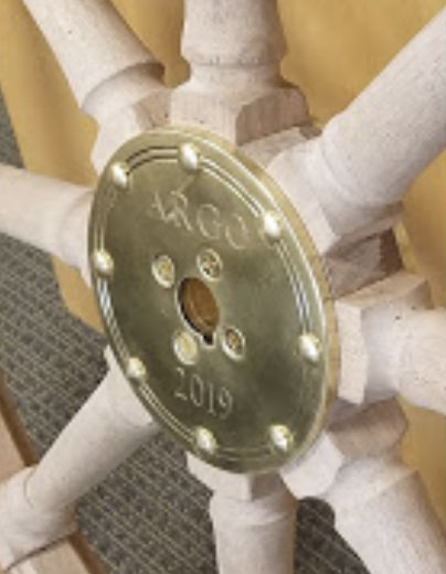
|
|
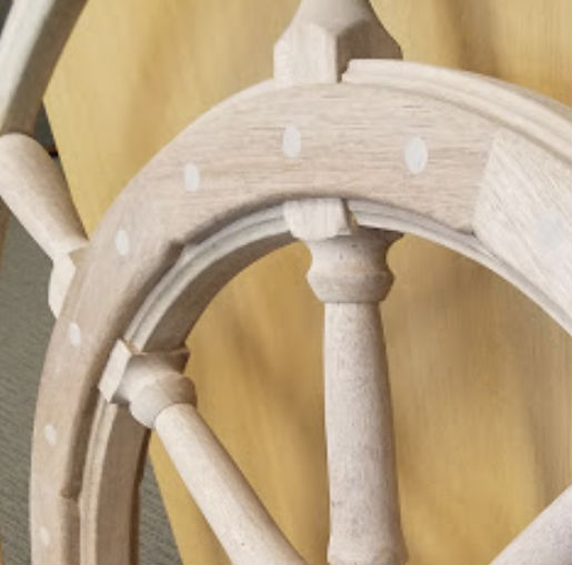
Close-up of center section
|

|
|
Finished supports
|
For the next part of the project, I needed to fit the supports onto the wheel. The supports
strengthen the joint between the spokes and the spacers. The supports straddle the spoke and
extend to the center of the spacers on each side of the spoke.
To cut the radii I used the same technique as for the spacers. Because the spokes were thicker
than the spacers I had to plow a groove in the middle of the support. I made a jig that indexed
the support and plowed the groove on the table saw. After I glued them on I drilled three holes
in each one and doweled them.
The last part of the project consisted of bending a ring of wood to fit around the wheel. I have
done a couple steam bending projects before so I have a duct work steam container. I built a
form on my bench that I could clamp the wood to. I decided to use white oak for its exterior
qualities and because I knew I could purchase it with straight grain. The first piece I used was 1"
x 1.5". I thought I could bend the whole piece. It snapped. I tried again but steamed it twice as
long. It snapped. Plan C was to steam 5 – 1/4" pieces. This worked great. I clamped each piece on
the form, cut a scarf joint and let it dry for several days. After it was dry I glued it together and
clamped it again. As with every part of this project, Poseidon was smiling upon me, and the
finished ring fit on the wheel like a glove. The ring was glued and doweled to the handles.

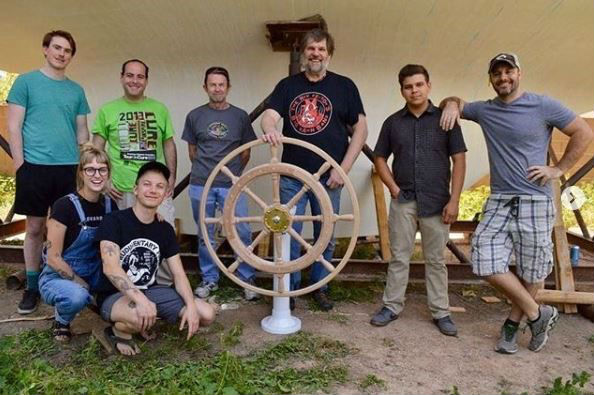
|
Part of the Argo crew with the author and now ship wheel builder
in the middle.
|
This was a wonderful project to tackle. Every phase of it posed new problems that I had to think
through. I used many woodworking techniques and layout strategies I was not familiar with. I
enjoy thinking about my son standing behind the wheel, sailing across the Pacific. If you want to
see more pictures of the Argo they have an Instagram page called
@rsv_argo
. If you want to see
more of my woodworking projects check out
www.qualitycraftsmanship.us
.
Return to the
Wood News Online
front page
|
|
|
|
|